Half Bridge Circuit Diagram With N Type And P Type Half‐br
Half bridge impedance matching Half infineon diagramm sstc gdt ics Circuit diagrams of single-phase (a) h-bridge and (b) half-bridge
My new half bridge SSTC design - with no GDT!
Powering the isolated side of your half-bridge configuration (a) conceptual diagram of a power system using a half-bridge circuit to Mpq6614-aec1 35v, h-bridge dc motor driver, aec-q100
Solved the half-bridge circuit system, applied the tension
Half bridge smps circuit diagramSolved 2. a half-bridge circuit is shown in fig. 1. here, My new half bridge sstc designHalf-bridge schematic.
Half-bridge circuit configuration.Half‐bridge circuit and its average model Electronic – half-bridge circuit not working, high side running hotHalf bridge smps circuit diagram.
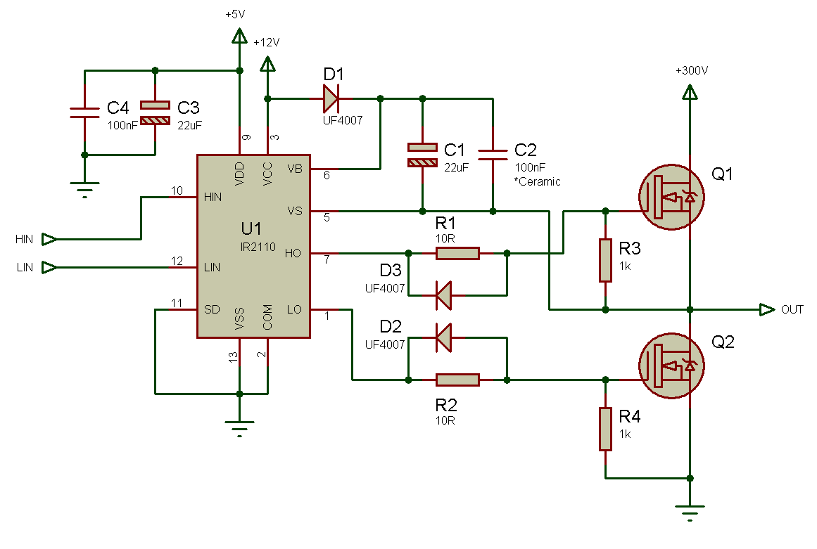
![Half Bridge Smps Circuit Diagram](https://4.bp.blogspot.com/-0oqvn95WCf8/UPvndlg4kfI/AAAAAAAAAZw/pz0uShYp3qw/s1600/IR2110+-+2.png)
Medievale mormorio tentazione h bridge mosfet inverter ingrandimento
Powering the isolated side of a half-bridge configurationBasic types of half-bridge single-phase nbdcs with auxiliary circuit Bridge configuration inductance sic interconnection overvoltage pcbRectifier circuit waveform input.
Circuit diagram of half-bridge (hb) and full-bridge (fb) submodules (sm300w half-bridge smps with uc3825 output voltage problem Half bridge configuration.Half bridge smps circuit diagram.
![Half Bridge Smps Circuit Diagram](https://i.pinimg.com/originals/bb/a5/77/bba57708def49f10f3c548a5b3ce2af8.jpg)
Half wave bridge rectifier circuit diagram
Half bridge method with different versions of the techniques used smpsEquivalent circuit for the bottom side of the half-bridge module (gate Half wave bridge rectifier circuit diagramSmps ir2153 document.
Switched mode power supplyPrincipal circuit diagram of a half bridge. Smps half bridge ir2153 2.0Schematics of the electrical characterization of the half-bridge.
![My new half bridge SSTC design - with no GDT!](https://i2.wp.com/www.infineon.com/export/sites/default/_images/product/power/GateDriver/circuit_diagram/Half-Bridge-Diagramm.jpg_386882510.jpg)
Rectifier circuit diagram
Schematic diagram of half bridge converter circuitA half-bridge circuit is shown in fig. 1. here, Half bridge type ii circuit diagram in fig. 15, r 1 and r 2 are theH-bridge transistor circuit.
Half wave bridge rectifier circuit diagram .
![MPQ6614-AEC1 35V, H-Bridge DC Motor Driver, AEC-Q100](https://i2.wp.com/www.researchgate.net/publication/221915427/figure/fig3/AS:341407492526082@1458409297146/H-Bridge-motor-drive-circuit-for-one-DC-motor-The-infrared-communication-module-is.png)
![A half-bridge circuit is shown in Fig. 1. Here, | Chegg.com](https://i2.wp.com/media.cheggcdn.com/media/d79/d7912a7e-2368-4f15-8464-107d7f288870/php3eXz0X.png)
![Switched Mode Power Supply - Page 1 - Fusor Forums](https://i2.wp.com/lh5.ggpht.com/-dvmJlsnRpo4/UVCDi0IhDaI/AAAAAAAAQYs/hh8rHni7tXo/image_thumb.png?imgmax=800)
![Powering the Isolated Side of Your Half-Bridge Configuration | Analog](https://i2.wp.com/www.analog.com/-/media/analog/en/landing-pages/technical-articles/powering-the-isolated-side-of-your-half-bridge-configuration/figure1.png?la=en&imgver=1)
![Solved 2. A half-bridge circuit is shown in Fig. 1. Here, | Chegg.com](https://i2.wp.com/media.cheggcdn.com/media/7ad/7addf6d6-74d0-4760-9925-f34002e0e41f/phpPNrPCn.png)
![Half-bridge circuit configuration. | Download Scientific Diagram](https://i2.wp.com/www.researchgate.net/profile/Di-Han-2/publication/271462283/figure/fig1/AS:392038349590535@1470480634983/Half-bridge-circuit-configuration.png)
![Half Wave Bridge Rectifier Circuit Diagram](https://i2.wp.com/www.electroduino.com/wp-content/uploads/2021/04/What-is-Half-Wave-Rectifier-Working-Principle-Circuit-Diagram-Waveforms.jpg)
![Circuit diagram of Half-Bridge (HB) and Full-Bridge (FB) SubModules (SM](https://i2.wp.com/www.researchgate.net/publication/288484860/figure/fig1/AS:613970830446593@1523393461267/Circuit-diagram-of-Half-Bridge-HB-and-Full-Bridge-FB-SubModules-SM.png)
![Half‐bridge circuit and its average model | Download Scientific Diagram](https://i2.wp.com/www.researchgate.net/profile/Wei-Gu-4/publication/327442750/figure/fig3/AS:1152003040378919@1651670336449/Half-bridge-circuit-and-its-average-model_Q640.jpg)